
- Details
- Written by: BMRC Admin
- Category: Club Projects
- Hits: 2181
Introduction
Back in October 2022 disaster struck with the Industrial Board, the raspberry pi that was the controller for the board failed, it fried its' self meaning that the Industrial board was now no longer usable. The price, and availability, of a replacement Raspberry pi, coupled with feedback from many members meant that it was time to re-consider how the Industrial Board was to be controlled and a project to replace the raspberry pi with a new control box was started in 2023.
Design Objectives
- To support eight (8) segments organised into four (4) tracks and eighteen (18) points.
- To be entirely powered from a standard ATX PC power supply.
- To be electrically compatible with the control system connector (5-way DIN) on the existing Industrial Board.
- To use the same control protocols (I2C) as the existing Industrial Board, no changes permitted.
- To allow the speed and direction of the trains to be independently controlled via physical switches and control knobs.
- To allow the position of the points to be independently controlled via physical switches.
- To provide visual feedback of the position of the points, the speed and direction of the trains on the tracks,
Hardware
The hardware designed for the new method of controlling the Industrial Board is in two parts, the wooden box and the electronics to read user inputs, drive the Industrial board and provide status feedback to the user.
The physical (wooden) box
The physical control box was made by a club member who does wood carving as a hobby and the design of the box is modeled on the physical control box of the 10-foot Main board, albeit a little taller. The basic design is to have a sloping front panel, hinged at the top, that would be used to both capture inputs from the user and provide status outputs. The board was designed to be large enough to hold a standard ATX PC power supply (the chosen power source) along with all the components needed to provide control commands to the Industrial Board via the I2C bus and due to power requirements, the box would need to include passive ventilation. The design of the box was started around mid 2023 and was completed by the end of July 2023 ready for the control electronics and PSU to be fitted.
The control electronics
The control electronics had to be compatible with the existing Industrial board, which was out of scope for any major changes or upgrade, so had to rely on the same control method (I2C) and be driven from 12VDC. As part of this project one minor change to the Industrial Board was made, to separate out how the 12VDC was used to drive the decoder logic, CDU and track power. The decision was made to power the CDU and track power from the same 12VDC line and have a separate 12VDC line for the control logic, this proved to be a very wise decision as it allowed the power to the track controllers to be varied to provide a "boost" for old/heavier locomotives.
User inputs
One of the main objectives for the new control box was to provide a more physical way of controlling the train direction, speed and track points, as follows:
- SPST momentary on push switch - one for each point, when pressed the position of the point would be toggled.
- SPDT centre off toggle switch - one for each of the tracks, allowing a direction of forward, reverse or off to be selected for each track.
- Rotary control knob - one for each track to allow the speed to be changed from zero (min) to 100% (max).
User feedback
Another of the main objectives for the new control box was to provide physical feedback on the status of the trains and points on the board, as follows:
- bi-colour (red/green) LEDs - one for each point, show RED when the point is in the "branch" position and GREEN when the point is in the "main-line" position.
- 4 line 16 character LCD - each line of the LCD shows the speed and direction of each track.
Logic control
The previous control box was based around a Raspberry Pi, the decision made was to move away from a raspberry pi, due to boot times, and use an ESP32 micro-controller. The ESP32 was coupled with an I2C buffer driver (TCA4307) to help boost the signal to the Industrial Board and better protect the micro-controller from voltage spikes and current surges. In addition to help with diving the LEDs and the LCD an MAX7219 and PCF8574 were used, along with an MCP23017 and a ADS1115 used to read the input switches and speed control knobs.

Block diagram of Control Board sub-systems

Front Panel Outside view

Front Panel inside view

ESP32 Microcontroller

Switch Scanner and RTC

LED Matrix Driver

Switch wiring matrix

Control Box inside view (ATX power supply and track voltage booster)

Control Box rear view
This completed the hardware in the control box, the following section talks about the control software that runs on the ESP32.
Software
The original control software was written in python for the raspberry pi and used pygame to handle all the user interface elements. The ESP32 microcontroller chosen was able to run micropython which is compatible with cython so the decision was made to port the existing code and structure the new code as follows:-
- ads1x15.py - Ported from python3, this module handles the low level interactions with the ADS1115 ADC.
- controlbox.py - This is the main flow for the application and was updated to remove all reference to pygame, keyboard, and mouse control and replace with logic to read the switches and screen controllers, then based on logic drive the points and track speed controllers.
- displaykeypaddriver.py - Written to provide a layer of abstraction to read the key presses and write to the display
- ds3231.py - Ported from python3, this module handles the low level interactions with the DS3231 RTC
- i2c_lcd.py - Written to provide a layer of abstraction to write text strings to the LCD
- industrialboarddriver.py - The module that provides a level of abstraction to drive the Industrial Board
- lcd_api.py - Written to provide a layer of abstraction to write text strings to the LCD
- logging.py - Written to provide a method to record any events in the program (info, debug, warning, error) and write then to a text file in a standard format
- main.py - This is the bootloader, first called following power-up, that allows either the main program (controlbox.py) to be executed, or the code exit and drop back to REPL
- max7219.py - Ported from python3, this module handles the low level interactions with the MAX7219 Display driver.
- MCP23017.py - Ported from python3, this module handles the low level interactions with the MCP23017 I2C Expander.
- PCA9685.py - Ported from python3, this module handles the low level interactions with the PCA9685 I2C PWM controller.
User Interface
There is no graphical user interface to this control box, the interaction with the user happens through the switches and control knobs, with the user will change the state of in response to what the train is doing, the position of the points and the status shown on the LCD. The main program (controlbox.py) runs an infinite loop as follows:
- while (True):
- read the status of the switches
- read the status of the control knobs
- update the position of the points based on the state of the switches
- update the track speed and direction based on the state of the switches and control knobs
- update the point LEDs with the status of the points
- update the LCD with the direction and speed of track
- wait a short amount of time
In the current implementation the loop described above loops approximately 3 times a second.
Board control logic
The bulk of the logic to control the points and track direction/speed is contained within the "industrialboarddriver.py" file and is designed to provide a level of abstraction between the hardware that controls the board (ADS1115 ADC, MCP23017 I2C Expander, PCA9685 I2C PWM controller) and by its' nature is complex. the file exposes three classes:
- class channel(object): Provides primitives to allow the ADC channel to be linked to the track segments
- class PowerDriver(object): Provides the methods to allow the speed and direction of the tracks to be controlled.
- class PointDriver(object): Provides the methods to operate the points.
- class ProximitySensors(object): This class is obsolete and not use in the ESP32 implementation.
The exact function of the class above are complex and beyond the scope of this article, for more information on the function the source code should be reviewed, which is available upon request.
- Details
- Written by: BMRC Admin
- Category: Club Projects
- Hits: 24175
The Winter Wonderland Board has now been dismantled and will be re-used in a future project.
The board was the Clubs first attempt at building a smaller board that could be used for Fayres.
It featured two loops of track mounted on a white fabric that looked like snow.
A PIC based controller switched on the two tracks and some track side lights for a random period following the push of a single button.
To save costs, the majority of the electronics from this board have made their way into the The Folding Board.
The remainder of the electronics (proximity sensors) will likely be used on the The Industrial Board.
- Details
- Written by: BMRC Admin
- Category: Club Projects
- Hits: 3680
Background
A demonstration was given using a PIC Microcontroller simulator that showed how a train travelling around a track anti-clockwise could be guided onto an inner track via a set of points. The position of the train was determined by a proximity sensor. Logic was written in the PIC to control the points based on the detected position of the train. The logic worked as follows:-
- Direct a single train anti-clockwise around an outer track five times.
- Direct a single train anti-clockwise around an inner track five times.
Brief
To prove that the PIC microcontroller demonstration can be realised on a real track, using real hardware and trains.
A PDF of this build log can be downloaded here.
Components
|
Item |
# |
Description |
|||||||||||||||||||||||||||
|
Hardboard |
1 |
SUNDEALA works well for this (Dimensions 3' x 6') |
|||||||||||||||||||||||||||
|
2 inch x 1 inch 3m wood |
AR |
Make an enclosed HH frame to add strength to the board |
|||||||||||||||||||||||||||
|
Wood Screws |
AR |
Wood screws to fix the support braces to the SUNDEALA |
|||||||||||||||||||||||||||
|
00 Gauge Track |
AR |
Enough to make a double loop |
|||||||||||||||||||||||||||
|
IR Proximity Sensors |
3 |
- |
|||||||||||||||||||||||||||
|
Hornby Point Motors |
2 |
R8014 - Point Motor and R8015 - Point Motor Housing (Adaptor Base) |
|||||||||||||||||||||||||||
|
CDU |
1 |
- |
|||||||||||||||||||||||||||
|
PIC IO Dev Board |
1 |
- |
|||||||||||||||||||||||||||
|
Power Jack (2.1mm) |
1 |
Maplin Order Code: HH60Q |
|||||||||||||||||||||||||||
|
PIC16F628A |
2 |
- |
|||||||||||||||||||||||||||
|
Red Wire |
10m |
Maplin Order Code: FA33L |
|||||||||||||||||||||||||||
|
Blue Wire |
10m |
Maplin Order Code: FA27E |
|||||||||||||||||||||||||||
|
Black Wire |
10m |
Maplin Order Code: FA26D |
|||||||||||||||||||||||||||
|
12VDC Regulator Board |
1 |
|
|||||||||||||||||||||||||||
|
Train controller |
1 |
Hornby R8012 HM 2000 Dual Power Controller |
Table 1: Bill of materials
Part One - Hardware
Building the board (120m)
Firstly construct an enclosed 'H' support brace around the perimeter of the board, with two braces that run left to right across the board. It is important to place the braces such that the 1 inch side it screwed to the board and the 2 inch side is at right angles to the board. This both allows strength and provides protection to the control electronics. Cut two holes in each of the braces to allow cables to pass through.
Laying the track (30m)
Once the braces have been fitted the track can be laid. The exact position of the track is not important, only that there is an inner loop and an outer loop.
Fitting the Electronics (180m)
The electronics can now be fitted to the board in three parts. The first and most difficult part is fitting the IRDOT-2D proximity sensors to the board underneath the tracks.
Proximity Sensors (60m)
Tools required: 4mm wood drill bit, 4mm circular file, 10mm rectangular file.
Using the 4mm drill bit, drill a hole from the top of the board between two of the sleepers on the track as a guide (Be careful at this stage to make sure that the sleeper is not damaged by the drill)
Remove the excess wood splinters from the underside of the board and place the circular file through the hole to clean and clear it.
Gently drag the circular file left in the circular hole to make it rectangular and large enough to put the 10mm rectangular file in.
Using the rectangular file widen the hole so that it is the width of the gap between the sleepers and no more than 10mm long (it should look like a letter box).
Remove the excess splinters from the underside of the board.
Place the IRDOT-2D below the rectangular letter box hole such that the IR transmitter and received slot into the hole but do not stick up above the sleeper (it may be necessary to file the hole slights to get a good fit).
Once the PCB is in place measure the distance between it and the underside of the board to enable spacers to be selected (and cut if required).
Secure the PCB to the track board using the required spacers ensuring that the holes required to hold the spacer to the track board do not foul the track.
Repeat for the other two IRDOT-2D sensors.
Control Circuits (15m)
Tools Required: Philips Screw Driver, Pliers, M3 bolts (3cm long), M3 nuts.
The position of the PIC IO-Board, CDU and 12VDC Regulator board is not critical and should be mounted close to the Proximity sensors, but avoiding where the Point Motors will go.
Note: The PIC-IO Board, CDU and 12VDC Regulator board should be mounted directly to the underside of the track board WITHOUT spacers. This firstly gives more clearance of the high capacitor components and secondly ensures the board does not flex during wiring.
Note: In order to aid program de-bugging do not obscure the RS232 port on the PIC IO Board.
Point Motors (15m)
Tools Required: Philips Screw Driver, Phillips countersunk screws (supplied).
Fit the two point motors on the top of the track board next to the points ensuring they are mounted level and the control levers are not fouled. Place a three connection terminal block next to the point motors to allow them to be easily removed and drill a small hole next to the terminal blocks for the wires to route to the underside of the board.
Wiring (90m)
Tools Required: Philips Screw Driver, Slot Screw driver, terminal blocks.
Wire the board as per the schematic (Appendix B), which was created using Eagle Lite Edition. There are no specific rules to wiring and what should be connected first, just try to stick to the following guides:-
- Use Red for positive or Point Motor Direction A.
- Use Black for negative or Point Motor Common.
- Use Blue for signal or Point Motor Direction B.
Note: Remember to check the wiring before power-up and use duck tape to secure loose cables to the underside of the board.
Power-up (5m)
Place the programmed PIC16F628A (Appendix A) into the PIC IO Board, and then connect the power. The RB5 Status LED should instantly light for five second and each of the IR Proximity sensors LEDs should also light up. After approximately four seconds the sensor lights should begin to switch off followed by RB5. The board will then pulse each relay output in turn to test the Point Motors. The board is ready for use.
Note: If any of the above does not happen remove power and double check the wiring.
Part Two - Software
Layout and Design
The software design was built using Dia and is shown in the figure below.
Development
The control software has been written in Microchip C using the MPLAB IDE and is modularised into components:-
main.c: This file contains the main track control algorithms.
track.c: This file contains the routines to control the board.
usart.c: This file contains the routines to communicate via the RS232 port.
track.h: This file contains the function headers and constant defines for track.c.
usart.h: This file contains the function headers and constant defines for usart.c.
The compile source code from the above five files is included in Appendix A as hex code ready for programming into a PIC16F628A using an appropriate programmer.
The software was programmed to the PIC16F628A using the Microchip PIC Start Plus as this is what the Author already had.
This is however a legacy product and Microchip recommend using the PICkit 2 Starter Kit instead.
Testing
The software has been tested using a PIC16 Simulator prior to being installed in the test track. The majority of the testing has been done on the Test Track board with the RS232 debug output connected to a laptop via an RS232 to USB converter running HyperTerminal under Windows XP Home SP3.
Part Three: Future Ideas
Diode Point switching
By using diodes connected to the drive relays and re-wiring the common from the Point Motors it would be possible to use three relays to drive two points rather than four relays to drive two points. This would then free up the fourth relay to control something else.
Auxiliary control
Once Diode point switching has been put in place, the fourth relay could be used to switch signals, power to track sidings, turn table motors, special effects units, etc to enhance realism of the layout.
- Details
- Written by: BMRC Admin
- Category: Club Projects
- Hits: 6603
Brief
Based on the Winter Wonderland board, construct a new board the folds for easy transport and has a PIC controlled system incorporating a game for children.
A PDF of this build log can be downloaded here.
Components
|
Item |
# |
Description |
|||||||||||||||||||||||||||
|
00 Gauge Track |
AR |
Enough to make two loops on the board including a siding loop |
|||||||||||||||||||||||||||
|
00 Gauge Points, Left Hand |
1 |
A single 00 Gauge point, left hand |
|||||||||||||||||||||||||||
|
00 Gauge Points, Right Hand |
1 |
A single 00 Gauge point, right hand |
|||||||||||||||||||||||||||
|
Hornby Point Motors |
2 |
R8014 - Point Motor and R8015 - Point Motor Housing (Adaptor Base) |
|||||||||||||||||||||||||||
|
9-way D-Type Plug |
2 |
Command connector for the Board and extension cable |
|||||||||||||||||||||||||||
|
9-way D-Type Socket |
2 |
Command connector for the control box and extension cable |
|||||||||||||||||||||||||||
|
6-way DIN Plug |
1 |
Power connector wired to the Dual Power Controller |
|||||||||||||||||||||||||||
|
6-way DIN Socket |
1 |
Power connector mounted to the Board |
|||||||||||||||||||||||||||
|
Black ABS Box 2x3x2 |
1 |
Box to contain the four control switches |
|||||||||||||||||||||||||||
|
Red Push-to-Make Switches |
2 |
Two red control switches for Start-Stop and Loop Isolate |
|||||||||||||||||||||||||||
|
Black Push-to-Make Switches |
2 |
Two black control switches for Siding-Park and Siding-Release |
|||||||||||||||||||||||||||
|
9-way D-Type Hood |
2 |
Hood for each end of the extension cable |
|||||||||||||||||||||||||||
|
25-way D-Type Plug |
1 |
Underside board connector to transfer power and points over the fold |
|||||||||||||||||||||||||||
|
25-way D-Type Socket |
1 |
Underside board connector to transfer power and points over the fold |
|||||||||||||||||||||||||||
|
25-way D-Type Hood |
2 |
Hood for each of the underside connectors |
|||||||||||||||||||||||||||
|
CDU |
1 |
||||||||||||||||||||||||||||
|
PIC IO Dev Board |
1 |
http://www.coolcomponents.co.uk/catalog/product_info.php?cPath=23_28&products_id=65 |
|||||||||||||||||||||||||||
|
Power Jack (2.1mm) |
1 |
http://www.maplin.co.uk/dc-power-plugs-43084 Order Code: HH60Q |
|||||||||||||||||||||||||||
|
PIC16F628A |
2 |
http://www.coolcomponents.co.uk/catalog/product_info.php?cPath=30_22&products_id=54 |
|||||||||||||||||||||||||||
|
Red Wire |
10m |
http://www.maplin.co.uk/equipment-wire-16-0.2-6197 Order Code: FA33L |
|||||||||||||||||||||||||||
|
Blue Wire |
10m |
http://www.maplin.co.uk/equipment-wire-16-0.2-6197 Order Code: FA27E |
|||||||||||||||||||||||||||
|
Black Wire |
10m |
http://www.maplin.co.uk/equipment-wire-16-0.2-6197 Order Code: FA26D |
|||||||||||||||||||||||||||
|
12VDC Regulator Board |
1 |
|
|||||||||||||||||||||||||||
|
Train controller |
1 |
Hornby R8012 HM 2000 Dual Power Controller |
Table 1: Bill of materials
Part One - Hardware
Building the board
The most complicated part of the construction is making the folding base board. The board must be light and flexible to be hinged, but sufficiently sturdy to mount the track and control electronics. The decision was made to design the board to make it easy to fold, transport and erect with the electronics being fitted later.
Laying the track
Lay the track onto the board so that the following layout is created.
Fitting the Electronics
The electronics can now be fitted to the board in the following order
1: Control Board and sockets
2: Point Motors
3: Power Transfer connector
4: Control Connectors
5: Wiring runs
Control Board and sockets
The PIC-IO-Board, CDU and point switches (Darlington Pair open collector) were all wired to a piece of hardboard sheeting and tested in isolation. This was done to aid construction and to ensure that testing was made easier. The figure below shows the components mounted. Once tested the Control Board is then inserted into the Folding board. It was decided to place the Control Board in one corner of the board to simplify wiring. The figure below shows the Control Board mounted.
Point Motors
The holes for the points were made and then wired to the board. The figure below shows one of the points. The other point is mounted in a similar manner.
Power Transfer connector
The power Transfer connector was then wired and connected to the board using block connectors so as to not tension the wires. The two figures below shows how the Transfer connector is wired.
Control connectors
The connectors to bring power and allow the control box to be connected are then fitted to the board. The figure below shows how the power (6-way DIN) and command (9-way D-Type) is mounted. The Velcro to the right of the D-Type is used to hold the control box when not used.
Wiring runs
The points, track power, Transfer connectors and control board are then wired together. The two figures below show the complete wiring looms.
Part Two - Software
Development
The control software has been written in Microchip C using the MPLAB IDE (http://www.microchip.com/stellent/idcplg?IdcService=SS_GET_PAGE&nodeId=1406&dDocName=en019469&part=SW007002) and is modularised into components:-
main.c: This file contains the main track control algorithms.
track.c: This file contains the routines to control the board.
usart.c: This file contains the routines to communicate via the RS232 port.
track.h: This file contains the function headers and constant defines for track.c.
usart.h: This file contains the function headers and constant defines for usart.c.
The compile source code from the above five files is included in Appendix A as hex code ready for programming into a PIC16F628A using an appropriate programmer. The software was programmed to the PIC16F628A using the Microchip PIC Start Plus (http://www.microchip.com/stellent/idcplg?IdcService=SS_GET_PAGE&nodeId=1406&dDocName=en010020) as this is what the Author already had.
This is however a legacy product and Microchip recommend using the PICkit 2 Starter Kit (http://www.microchip.com/stellent/idcplg?IdcService=SS_GET_PAGE&nodeId=1406&dDocName=en023805&part=DV164120) instead.
Testing
The software has been tested using a PIC16 Simulator (http://www.oshonsoft.com/pic.html) prior to being installed in the test track.
The majority of the testing has been done on the Test Track board with the RS232 debug output connected to a laptop via an RS232 to USB converter running HyperTerminal under Windows XP Home SP3.
- Details
- Written by: BMRC Admin
- Category: Club Projects
- Hits: 7823
The story thus far
Much has been done over the last few years with the Extension board to the point where engines are now able to run on the board powered by new control system. This is significant milestone for the construction of the board as it has taken almost two years to get to this point!
Each of the 18 points work
Each of the 8 segment work and it was possible to drive a train around the three main loops using the track segment presets configured in the software.
What has been done?
Control Box
The Raspberry Pi Control has been moved to the underside of the board, the linear voltage regulator have been replaced with switch mode and it all works really well with the need for additional cooling. An old power supply from a laptop has been re-purpose to drive the Pi and the on board control logic which has resolved another problem identified in the prototype of load when both channel were active and a train stalled. The increase in current caused the voltage on the auxilary line to drop causing the Pi to crash and the system fail. Using a separate power supply increases the mains plug count, but it means that the dual channel speed controller is under less load so runs a little cooler.
Point Board
This has been constructed, but problems in prototype (see below) means that a secondary board needed to be designed to expand the capability.
Track Power Board
Back in 2018 and 2019 this board went through a significant upgrade that saw the removal of the reliance on old analogue controllers and a move to PWM control. Initial problems with older engines that caused the motor controllers to burn out due to excessive (4A+) current drain have now been resolved with current limiters and the board seems to now work well. Because the Track Power Board is now PWM and controlled directly by the raspberry pi it is now possible for automated drive sequences to be programmed as the speed and direction are no longer under the direct control of the operator.
Hardware changes (read lessons learnt during construction)

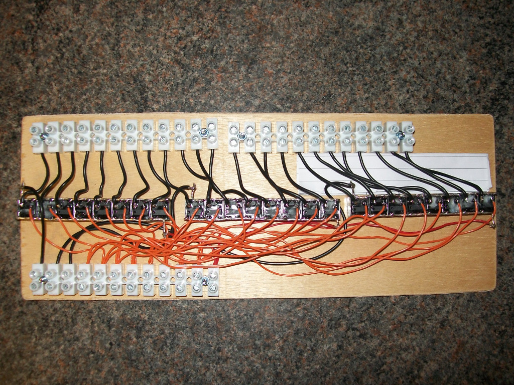
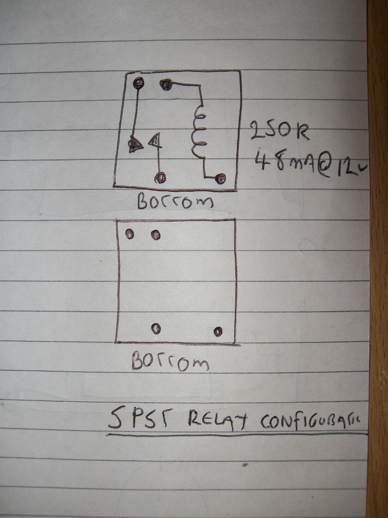
The physical layout of the board has not changed, but the techniques for controlling the points have needed to be updated to work around some problems found during early construction. The biggest problem found was around how to drive more than one point at the same time, something that because of the looped layout of the board will need to happen. Wiring the points in serial and parallel did not work correctly as either the points did not receive enough voltage or current to work correctly. The solution to this problem was simple, drive each point individually but expand the drive capability of the controller to run 24 individual points (with still spare capacity for more) rather than the previous limit of 15. A bulk purchase of relays from a popular auction site and some novel wiring soon gave the solution!
Software changes (read bugs in the code, changes to requirements)
The approach to controlling the board has changed, rather than having a Raspberry Pi performing the control in a 'headless' manner it was decided that it would be better to run the Pi with a Monitor and wireless Keyboard/Mouse. This design change has allowed the software written to be more sophisticated so a 'point-and-click' style interface with short-cut keys has been implemented in python.
What is left to do?
Hardware
Nothing .... the board, points and track are finished!
Software
The software contains lots of hard coded constant values for the point-and-click interface so these need to be moved out to a configuration file to make the software easier to read and a little more dynamic. This will be addressed through ongoing improvements and incremental releases.
Scenery
Of course once the hardware of the board is complete, it needs to be ballasted and the scenery and building added. The extension board has now reached this important milestone so this work can begin.
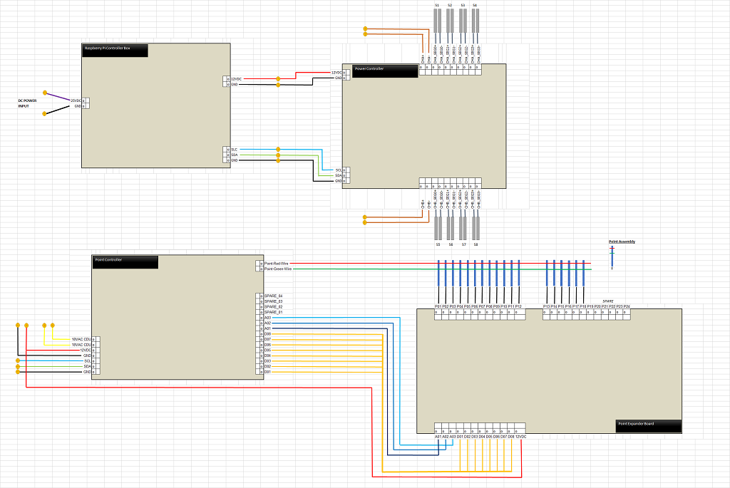
Wiring Diagram
For those interested in the construction of the board used to control the trains, below is the wiring diagram for the board.
What is next .... scenery
Work on the scenery can now start, check back here for more details and build logs.