![]()
Much has been done over the last few years with the Extension board to the point where engines are now able to run on the board powered by new control system. This is significant milestone for the construction of the board as it has taken almost two years to get to this point!
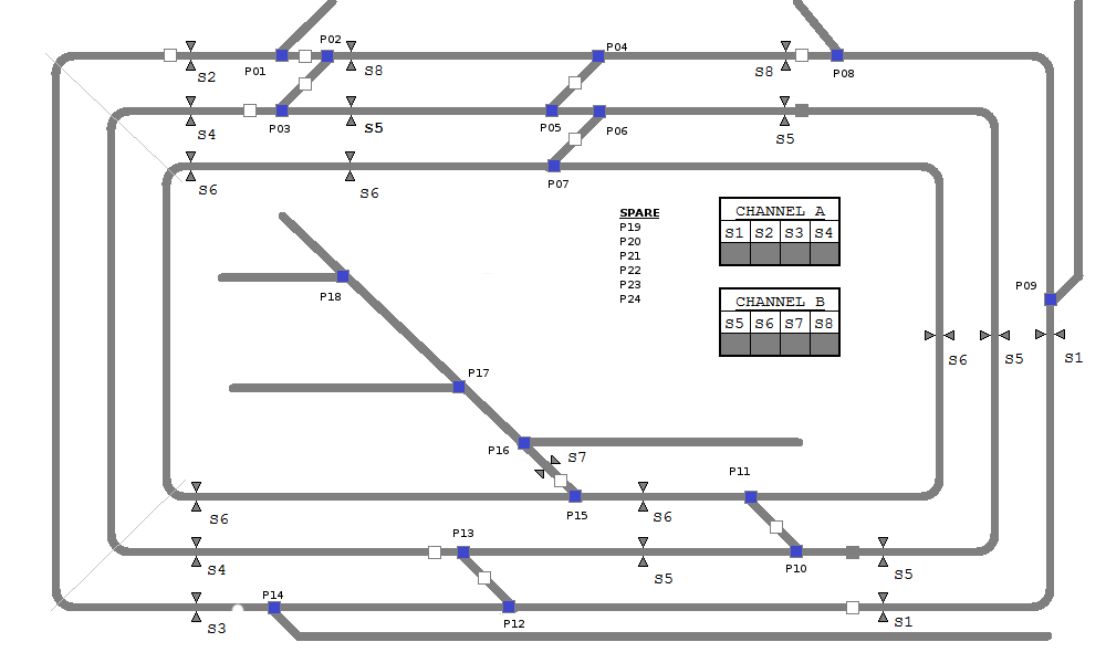
Each of the 18 points work
Each of the 8 segment work and it was possible to drive a train around the three main loops using the track segment presets configured in the software.
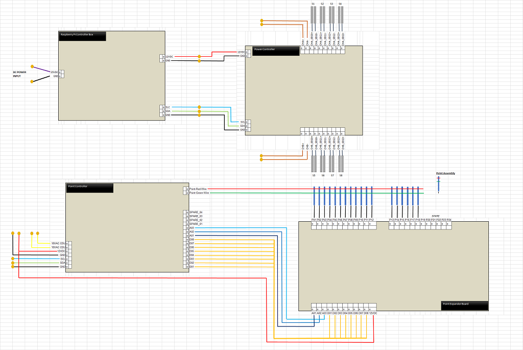
The Raspberry Pi Control has been moved to the underside of the board, the linear voltage regulator have been replaced with switch mode and it all works really well with the need for additional cooling. An old power supply from a laptop has been re-purpose to drive the Pi and the on board control logic which has resolved another problem identified in the prototype of load when both channel were active and a train stalled. The increase in current caused the voltage on the auxilary line to drop causing the Pi to crash and the system fail. Using a separate power supply increases the mains plug count, but it means that the dual channel speed controller is under less load so runs a little cooler.
This has been constructed, but problems in prototype (see below) means that a secondary board needed to be designed to expand the capability.
Back in 2018 and 2019 this board went through a significant upgrade that saw the removal of the reliance on old analogue controllers and a move to PWM control. Initial problems with older engines that caused the motor controllers to burn out due to excessive (4A+) current drain have now been resolved with current limiters and the board seems to now work well. Because the Track Power Board is now PWM and controlled directly by the raspberry pi it is now possible for automated drive sequences to be programmed as the speed and direction are no longer under the direct control of the operator.
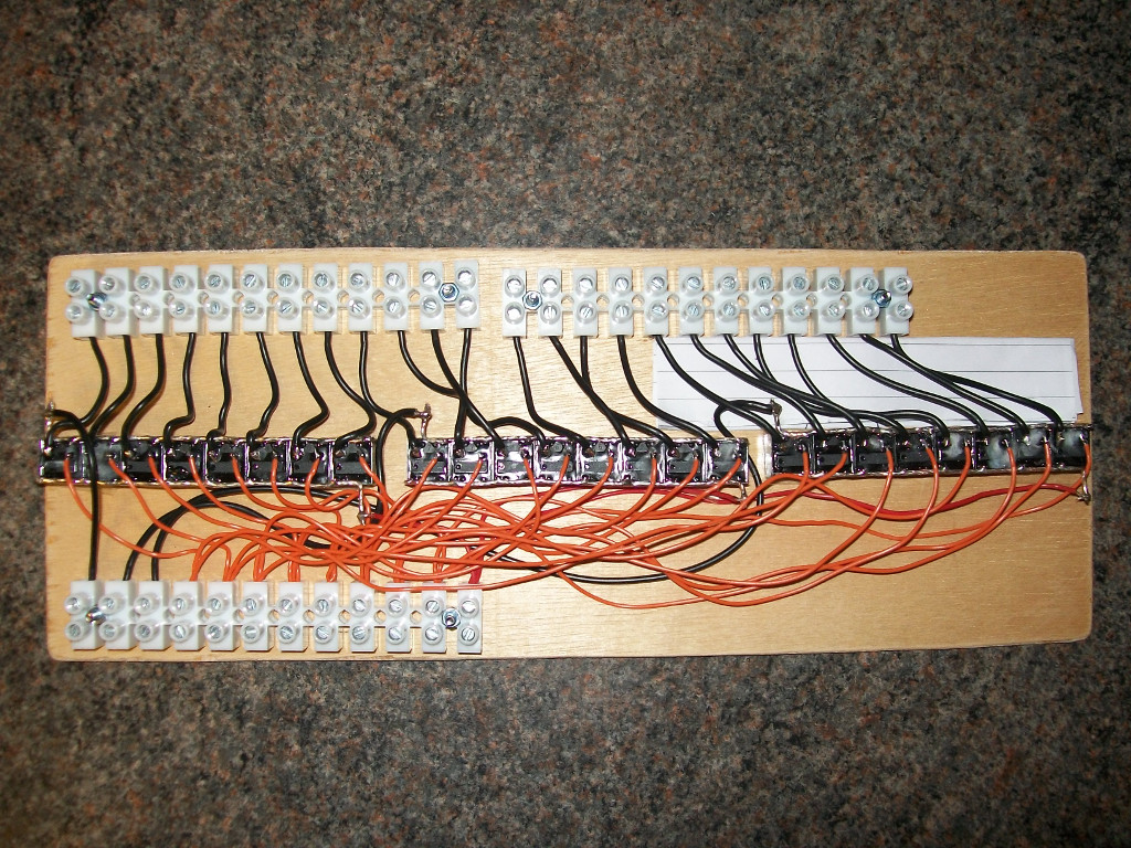
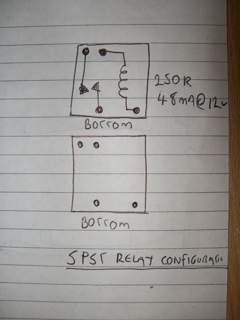
The physical layout of the board has not changed, but the techniques for controlling the points have needed to be updated to work around some problems found during early construction. The biggest problem found was around how to drive more than one point at the same time, something that because of the looped layout of the board will need to happen. Wiring the points in serial and parallel did not work correctly as either the points did not receive enough voltage or current to work correctly. The solution to this problem was simple, drive each point individually but expand the drive capability of the controller to run 24 individual points (with still spare capacity for more) rather than the previous limit of 15. A bulk purchase of relays from a popular auction site and some novel wiring soon gave the solution!
The approach to controlling the board has changed, rather than having a Raspberry Pi performing the control in a 'headless' manner it was decided that it would be better to run the Pi with a Monitor and wireless Keyboard/Mouse. This design change has allowed the software written to be more sophisticated so a 'point-and-click' style interface with short-cut keys has been implemented in python.
Nothing .... the board, points and track are finished!
The software contains lots of hard coded constant values for the point-and-click interface so these need to be moved out to a configuration file to make the software easier to read and a little more dynamic. This will be addressed through ongoing improvements and incremental releases.
Of course once the hardware of the board is complete, it needs to be ballasted and the scenery and building added. The extension board has now reached this important milestone so this work can begin.
For those interested in the construction of the board used to control the trains, below is the wiring diagram for the board.
Work on the scenery can now start, check back here for more details and build logs.
This document was last modified: .